The Wireless Valve Link enables wire-free valve control and monitoring for new, existing, and add-on valves in ICC2 or HCC control systems.
Get the WVL app to get started!
Battery Installation
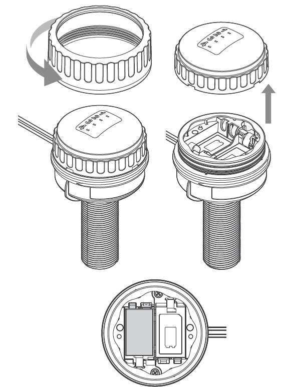
- Open the battery cover on the Wireless Valve Link. Unscrew the retaining ring, then remove the
waterproof cover. - Install one 9 V DC battery on the left side to allow easy access to the button on the right.
- Hold down the right button closest to wires for 2 seconds to enter assignment mode. The light will
flash yellow.
App Assignment
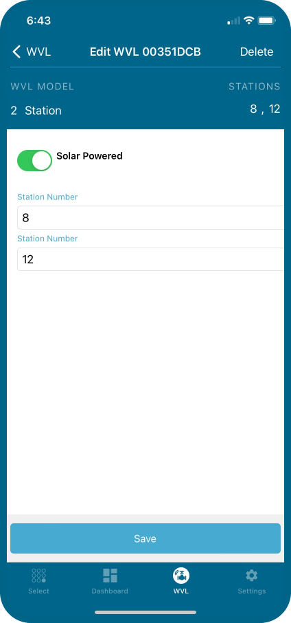
- Open the App within Bluetooth range of the Wireless Valve Output Module in the controller.
- Select the WVOM device from the list and click Connect.
- Select the WVL tab at the bottom.
- Use the app + Button to assign the station numbers and Save. If assigning an output as a Master Valve, refer to the wiring instructions here. The Wireless Valve Link assignment light will flash and turn off when programming is successful.
Second Battery Installation
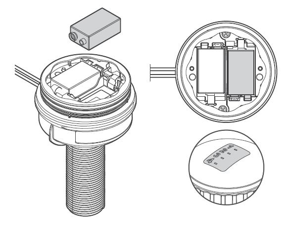
- Install a second 9 V DC battery. Write the station number on the Wireless Valve Link battery compartment.
- Reassemble the battery compartment. Push the cap down firmly. Make sure the O-rings are not misaligned and stay in their tracks. Then tighten the retaining ring (hand-tighten only).
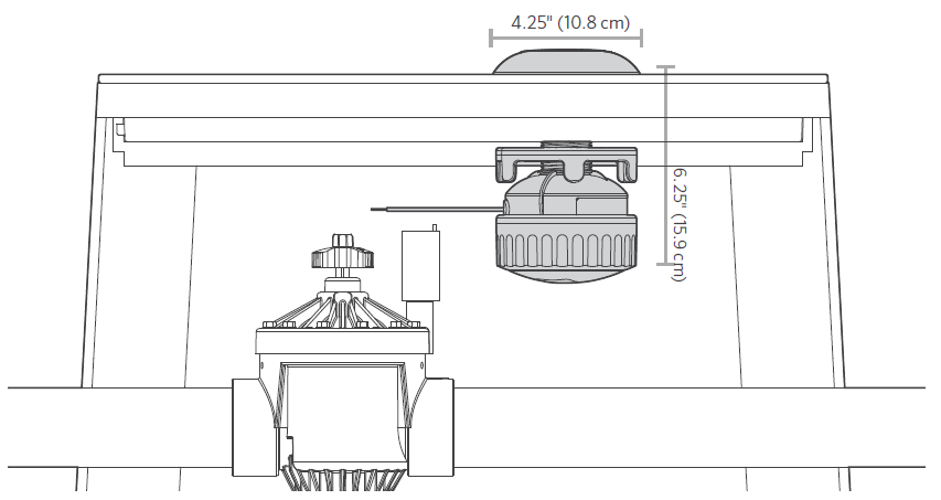
Valve Box Installation
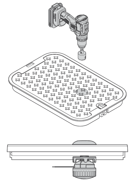
- Take the Wireless Valve Link to the valve box and determine where it will be located. Make sure it won't interfere with the valve, or install in its own valve box.
- Final installation requires a minimum 4.25" (10.8 cm) diameter and 6.25" (15.9 cm) vertical clearance below the valve box lid.
- Mark the location for the hole in the valve box lid. Use the hole saw supplied with the Wireless Valve Output Module to drill a 1.5" (38 cm) hole through the lid. A saw may be necessary to finish the cut through the lid’s support ribs.
- Insert the threaded column through the hole from the bottom, and secure with the cap above. Tighten supporting nut underneath.
DC Solenoid Installation
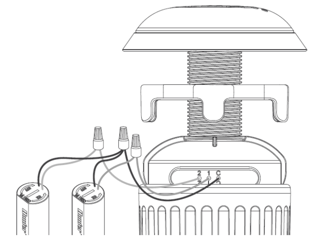
- Connect the numbered DC solenoid wires, red to red and black to black. Use only waterproof connectors.
- On multi-station versions, connect all black solenoid wires together with the black common from the Wireless Valve Link.
Still need help? We're here.
Tell us what you need support with and we'll find the best solution for you.