Electrical Data for Pilot FC & IH Model Controllers
FC (Field Controller) Model
| Power Type | Region | Voltage and Frequency | Current |
|---|---|---|---|
| Primary Power (Input) | US & Canada | 100 to 132 VAC, 50/60 Hz | 1.2 amps max |
| International | 200 to 260 VAC, 50/60 Hz | .73 amp max | |
| Secondary Power (Output) | All Regions | 24 VAC, 50/60 Hz | 1 amp per station max. 4 amps max. |
IH (Integrated Hub) Model
| Power Type | Region | Voltage and Frequency | Current |
|---|---|---|---|
| Primary Power (Input) | US & Canada | 100 to 132 VAC, 50/60 Hz | 5 amps max |
| International | 200 to 260 VAC, 50/60 Hz | 2.5 amps max | |
| Secondary Power (Output) | All Regions | 40 VAC, 1.2 Hz | 1.2 mA per Two-Way Module (idle). 45 mA per active solenoid |
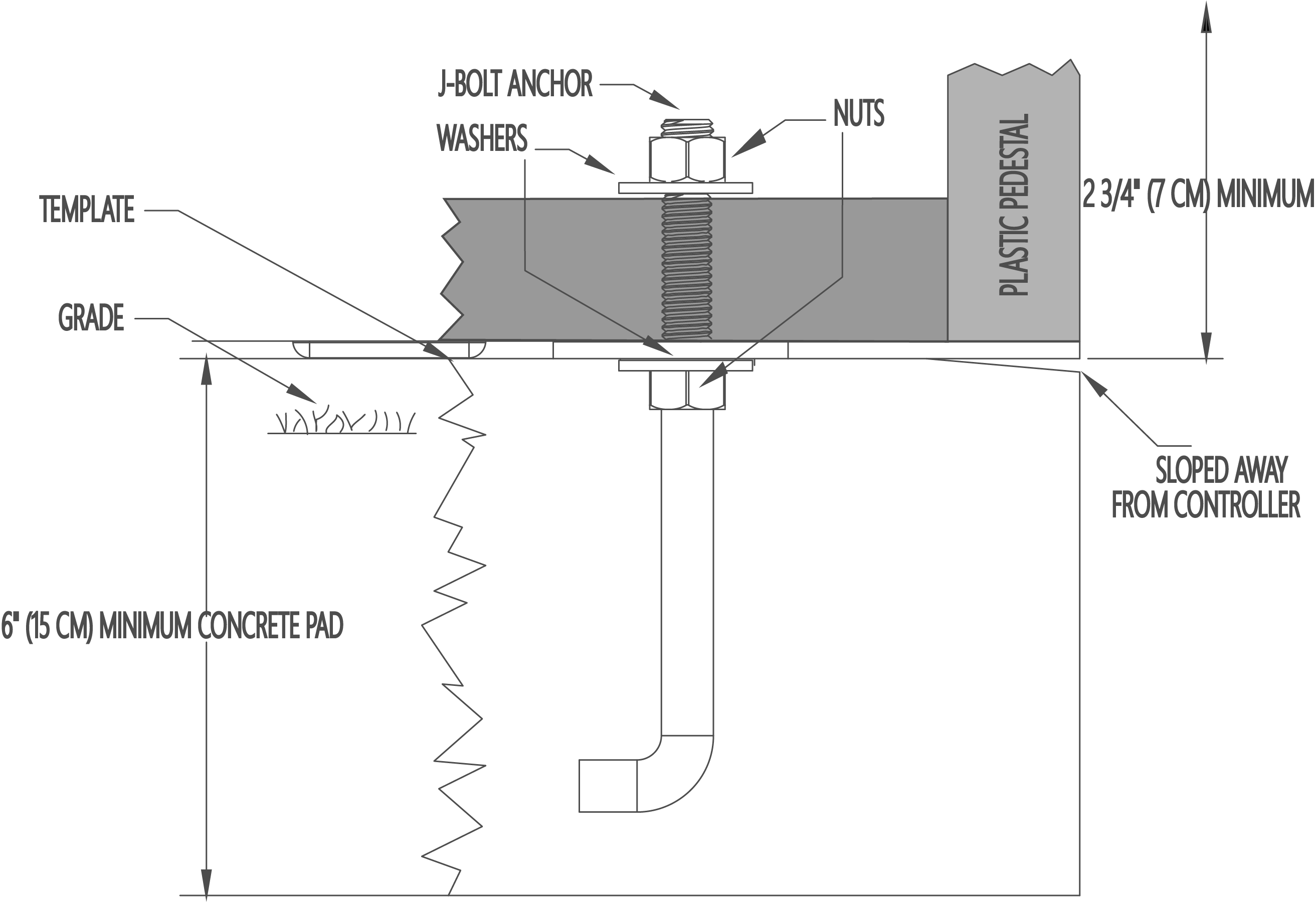
Installation
- Remove the nuts and washers from the concrete base.
- Place the controller over the template and J-bolts.
- Secure with the nuts and washers as shown below.
Wiring
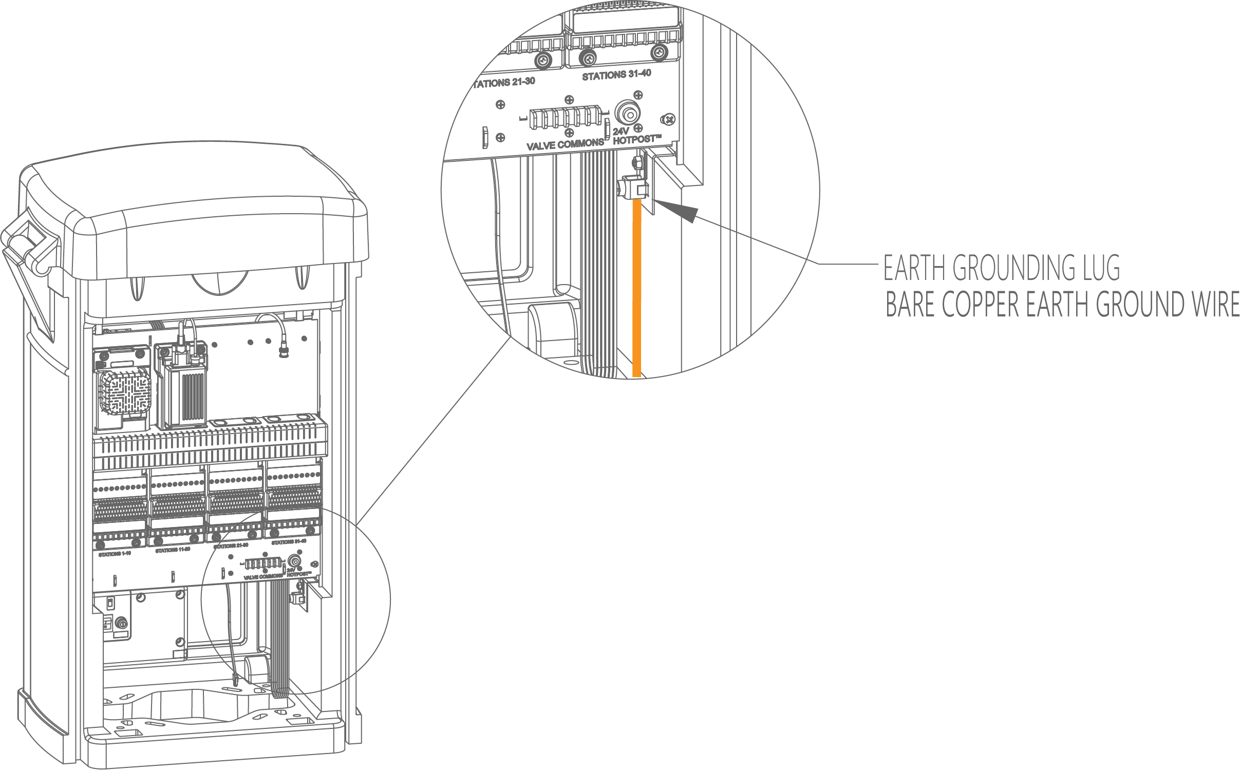
- To limit or prevent lightning damage to your equipment an earth ground system must be installed. The grounding system discharges lightning-induced current into the earth rather than allowing the surge to pass through the power or station wires and into your controller. Hunter recommends following the American Society of Irrigation Consultants Guidelines for earth-grounding electronic equipment in irrigation systems.
- After installing the controller's earth grounding grid, route a 6 AWG (10 mm2) bare copper wire up through the 1.5” (4 cm) conduit sweep elbow and into the controller, securing it to the copper ground lug as shown below.
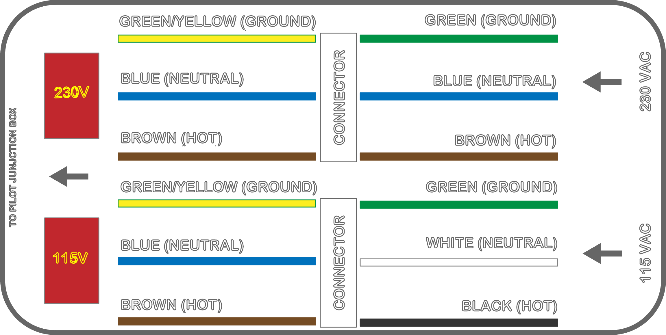
- Once the earth ground is complete bring the incoming AC power cable through the 1” (3 cm) incoming power conduit sweep elbow. Remove the cover from the AC power junction box and connect the wires as shown below. If the AC power wire continues to the next controller, bring the outgoing AC power cable up through the outgoing power conduit, sweep the elbow, and connect the wires as shown using appropriately sized wire nuts.
- Warning: While the controller power wire is being connected power at the source should be off.
- Important: The voltage selection switch is factory set to 230 VAC. Before applying AC power to the controller, ensure the switch is set to the appropriate voltage. For Integrated Hub controllers, there is no switch. The power supply senses the incoming voltage and does not need to be switched. Simply wire the incoming power supply to the controller.
- Replace the junction box cover.
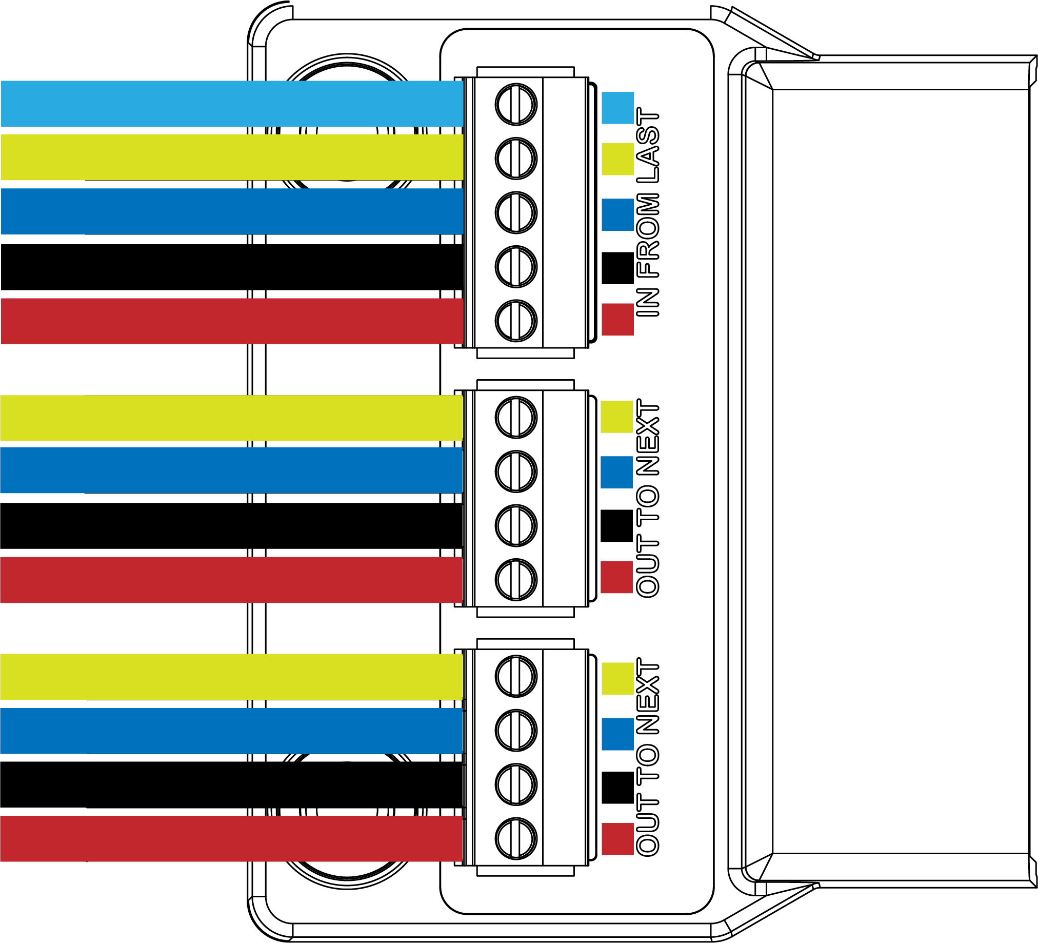
- Once AC power is connected bring the GCBL communication cable (if required) up through the 1” (2.5 cm) incoming GCBL conduit sweep elbow. If the GCBL continues to another controller(s), bring the outgoing cable(s) up through the same conduit.
- GCBL is a 4-conductor cable containing two twisted pairs of wires plus a ground wire. The ground wire should only be connected to the incoming cable – a five-terminal connector is provided. The four-terminal connectors are for cable going to the next controller(s). Do not connect the ground wire to the four-terminal connectors. Trim the ground wire back to the outer insulation.
- After wiring the connectors, route the GCBL cable up through the center of the controller between the sheet metal backplanes and plug the connectors into the Pilot-HWR hardwire communication module.
- Next, bring the station wires (two-wire or conventional) up through the 4” (10 cm) conduit sweep elbow.
- FC & IH Models
- FC: Station and common wire terminals for stations 1 through 40 for the FC are on the front of the controller. Station 1 is the leftmost terminal. Stations 41 to 80 are on the back. Station 41 is the leftmost terminal. Separate the valve and common wires appropriately.
- IH: Two-wire paths for Stations 1 through 999 are on the front of the controller for the IH. The first decoder module uses stations 1 through 250, second 251 through 500, third 501 through 750, and fourth 751 to 999. Any two-wire path can go into any of the 6 wire paths for the decoder modules as long as the two-way module address correlates with the capacity of the decoder module. For example, if a two-way module is programmed as station 563 it should be wired into the third decoder module. Separate the two-wire cables appropriately for easy installation and wire the cables to the correct decoder module. (Skip to step 12 for the IH)
- Connect all common wires for the FC to the common terminals before the station valve wires.
- After connecting all common wires to the common terminals provided for the FC, begin connecting the station wires. The Pilot FC controller includes a yellow 24 VAC HotPost™ adjacent to the common terminals. The HotPost™ is a constant 24 VAC output which can be used to verify stations before connecting them to the station terminals. Insert the stripped end of the station wire into the HotPost™. 24 VAC will be applied to that station for a direct visual of what station has been activated. After it's understood which station it is remove the wire from the HotPost™ and wire it to the appropriate station terminal.
- After all wires for the FC or IH have been connected to power on the controller, test its operation.
Still need help? We're here.
Tell us what you need support with and we'll find the best solution for you.