In this Quick Start Guide, you'll learn how to install and configure your flow meter. If you need Hydrawise® Software support or help with your Hydrawise account, visit our App support section. Learn More

Gaskets are available as spare parts. Visit your local dealer for purchasing details. Learn More
| Part Number | Description |
|---|---|
| 10021300SP | Qty. 10, HC-075-FLOW Spare Gaskets |
| 10021400SP | Qty. 10, HC-100-FLOW Spare Gaskets |
| 10021500SP | Qty. 2, HC-150-FLOW Spare Gaskets |
| 10021600SP | Qty. 2, HC-200-FLOW Spare Gaskets |
The flow meter consists of two parts:
- Flow meter body: The flow meter body contains an analog dial for manual readings as follows. Your flow meter will have three wires protruding from the body. The wires need to be connected to the sensor inputs on the controller for readings in the software application. Only two wires (blue and white) are used in all models.
- Adapter: Each flow meter has an adapter to allow for connection to your irrigation system.
| Dial Marking | Measurement Unit |
|---|---|
| X0.01 | 0.1 gal |
| X1 | 1 gal |
| X10 | 10 gal |
| X100 | 100 gal |

Note: The flow meter displays U.S. gallons. If desired, you can change the unit of measure in the app to liters.
Planning is an important step in the successful installation of your Hunter HC Flow Meter and the reliable operation of your irrigation system.
Flow meters are installed between the master valve and the zone valves. To avoid false alerts t s, there should be no water taps or other uncontrolled water use on the downstream side of the flow meter. If all solenoids connected to the controller are not grouped together, it may be necessary to install more than one flow meter. For proper installation and optimal water flow, use the chart below to determine the proper pipe length. The pipe bringing water into the flow meter needs to be 10 times longer than the width of the pipe, while the pipe carrying water away from the flow meter needs to be five times longer than the width of the pipe.
| Pipe | 10X-Before | 5X-After |
|---|---|---|
| ¾" | 7½" | 3¾" |
| 1" | 10" | 5" |
| 1½" | 15" | 7½" |
| 2" | 20" | 10" |
Cable (shielded direct-burial cable must be used): Two-wire cable is required. The cable gauge is determined by the total length of cable between the controller and the flow meter. The cable should consist of two dedicated wires and must not be in the same conduit or cable bunch as the solenoid wires. Do not share the common wire of the solenoids with the common wire of the sensors.
Flow Meter Cable Length Chart
| Wire Size | Max Length |
|---|---|
| 18 Guage | 1,000 Feet |
IMPORTANT: Shielded direct-burial cable is commonly available. Manufacturers include Paige Electric and Regency Wire.
The body of the flow meter includes an arrow-shaped marking that indicates the direction of the water flow. The flow meter must be installed in the correct orientation, with the water flowing in the same direction as the arrow on the flow meter body. All HC Flow Meters must be installed horizontally with the dial facing up.
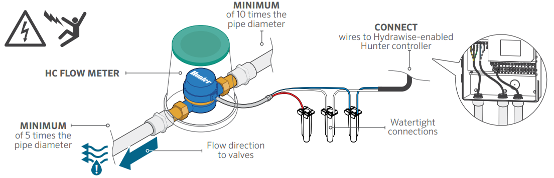
Two-wire cable is required to connect your flow meter. It mus t be solely designated for the flow meter and not shared with the common wire of the valves or other sensors. The cable gauge is determined by the total length of cable between the controller and the flow meter. Connect the wires to your Hydrawise-enabled Hunter controller.

- Log in to your account
- Create a flow sensor: It's important to select the correct model when configuring your flow meter in the Hydrawise App. Choosing the wrong model may result in false alerts within the software. Learn More
Still need help? We're here.
Tell us what you need support with and we'll find the best solution for you.