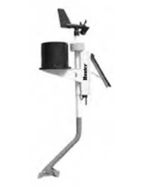
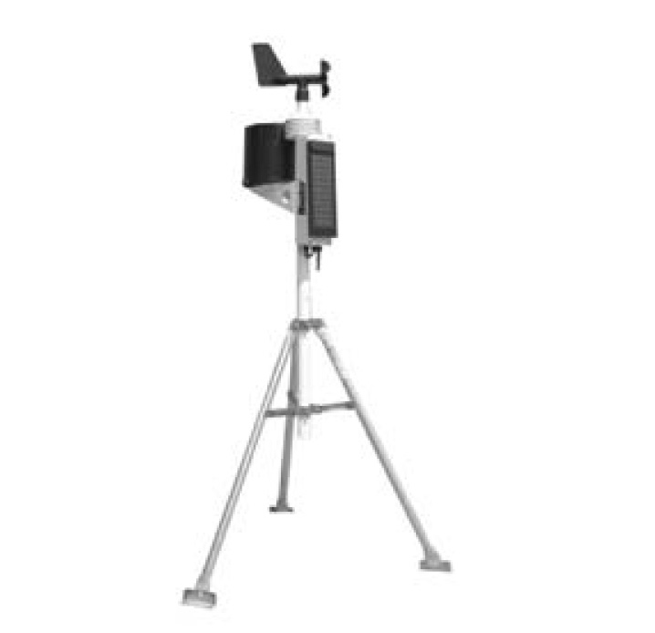
The sensor assembly has been designed to offer durability and serviceability. This sleek design is 33" (84 cm) high and weighs just over 7 lb (3.1 kg). It's the most accurate, durable, and easiest-to-install weather station available.
The sensor assembly has been designed to offer durability and serviceability. This sleek design is 33" (84 cm) high and weighs just over 7 lb (3.1 kg). It's the most accurate, durable, and easiest-to-install weather station available.
Before permanently installing your system, set it in the same room as your receiving device. Turn the system on and confirm successful communication.
Modbus® TCP/RTU Converter Connection
To connect a weather station Modbus converter, ensure proper communication between the weather station and the Modbus network using the following connection diagram:
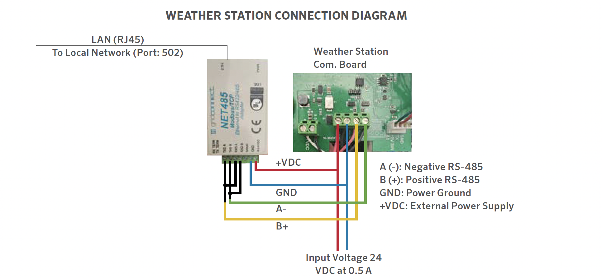
Connection Diagram
WEATHER STATION CONNECTION DIAGRAM
(Option 1)

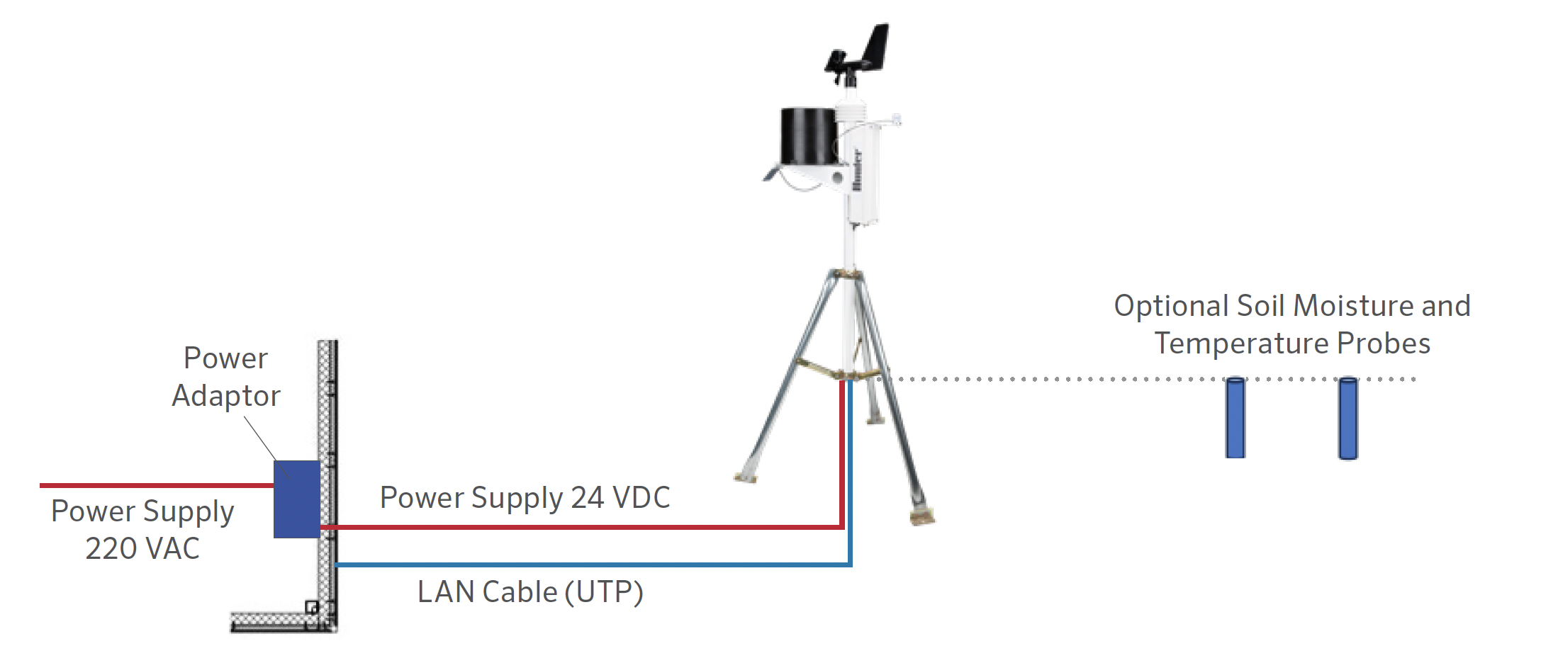
WEATHER STATION CONNECTION DIAGRAM
(Option 2)
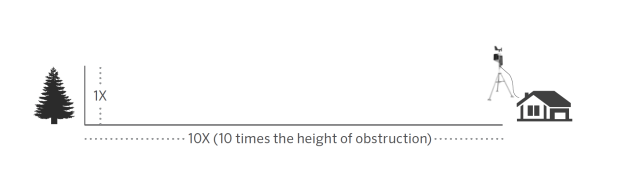
The best location for your weather station is one that is free of obstructions and at an elevation high enough to prevent interference to the anemometer (wind sensor) from nearby trees or buildings. The station should be no closer to an obstruction than 10 times the obstruction’s height.
The mounting mast included with your sensor assembly has an outside diameter of 1.69" (42.7 mm) and an inside diameter of 1.31" (33.4 mm). The length of the mast is 18" (45.7 cm). There are many ways to mount the system utilizing the mast.
Mono Mount
The mono mount and tripod are the most common methods of mounting. The mounting mast can be placed over another pipe, into another pipe, hose-clamped to a pipe or post, or drilled and through-bolted to a surface.
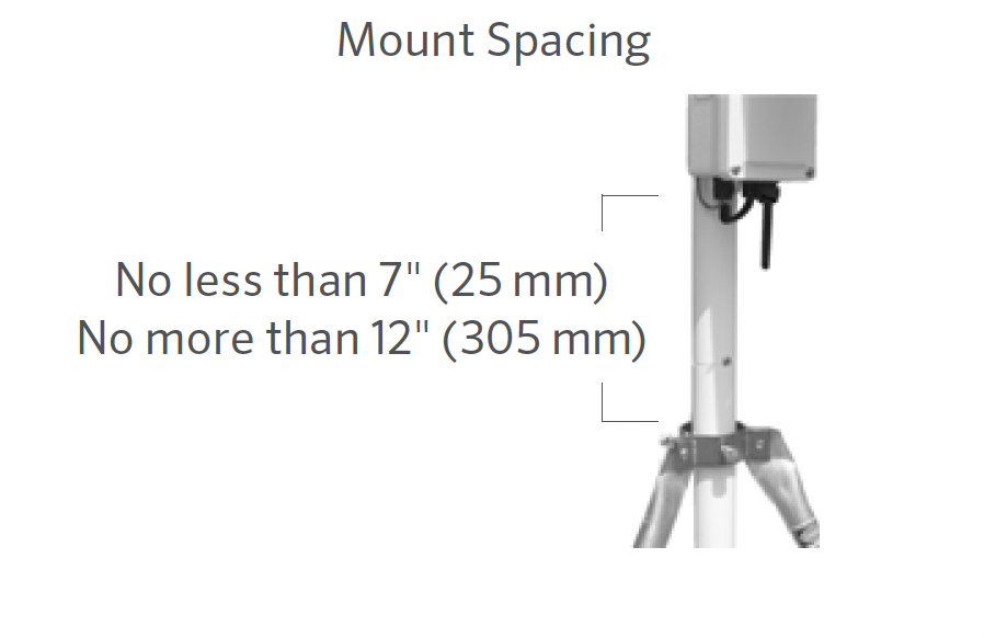
Regardless of how you mount the system, the bottom of the electronics enclosure should not extend more than 12" (20 cm) or less than 7" (17.8 cm) above the support of the mounting mast. The reason for this is the stability of the tipping bucket rain gauge; unintended movement may cause inaccurate rainfall counts.
The station should be free of obstructions or heat-absorbing items and should have a clear line of sight between the station and the receiving device.
Tripod Mount
Ensure the distance between the bottom of the control box and the tripod is no less than 7" (17.8 cm) and no more than 12" (20 cm).
Roof Mount
When roof-mounting the sensor assembly, the unit should be mounted toward the edge of the roof (preferably on the prevailing wind side of the building). It should be installed at least 2.5' (76 cm) above the roofline. Avoid locating the station near any heat sources such as chimneys or vents. The anemometer may be separated from the station and mounted separately, if necessary, to ensure that it is adequately free from interference.
- Secure the support tube in the desired mounting apparatus as described above. Slide the WS-360 Station down over the necked-down section of the support tube until seated and the slot lines up with the retaining screw. Tighten the screw.
- Rotate the station until the solar panel faces TRUE SOUTH in the Northern Hemisphere or TRUE NORTH in the Southern Hemisphere. Once positioned correctly, ensure that the support tube is secure and unable to rotate.
- Adjust the solar panel for optimum performance by tilting it to the appropriate angle and locking it into place with the bracket located behind it.
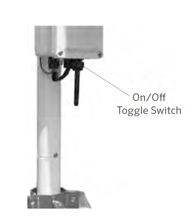
- Turn the system on by pulling the switch toward the solar panel.
Depending on the location of your system, the rain gauge may periodically get clogged with dirt, leaves, or other debris. When this happens, your rainfall data will appear significantly lower than other totals in your area or cease to record altogether. Clean the rain gauge as follows:
- Loosen the 4 screws holding the collector portion onto the base of the rain gauge.
- Twist the collector counterclockwise and remove it.
- Observe the cotter pin holding the plastic screen in place. Straighten the cotter pin legs to remove it along with the plastic screen.
- Clear debris from the screen, collector drain, and white dipper assembly.
- Visually inspect the small circuit board located beneath the white dipping assembly.
- Place the screen and cotter pin back in place and bend the cotter pin legs up and around the inlet as they were before. If they are not bent up and away from the tipper mechanism, they will prevent a complete tip.
- Replace the collector and tighten the 4 screws.
Methods of Assigning the IP Address
The unit's IP address must be configured before a network connection is available. You have several options for assigning an IP to your unit.
| Method | Description |
| Device Installer | You manually assign the IP address using a Graphical User Interface on a PC attached to the network. |
| Telnet | You manually assign the IP address and other network settings at a command prompt using a UNIX or Windows-based system. Only one person at a time can be logged into the configuration port (port 9999). This eliminates the possibility of several people simultaneously attempting to configure the unit. |
IP Address
Your weather station must have a unique IP address on your network. The systems administrator generally provides the IP address and corresponding subnet mask and gateway. The IP address must be within a valid range, unique to your network, and in the same subnet as your PC.
DHCP
The unit ships with a default IP address of 0.0.0.0, which automatically enables DHCP. Provided a DHCP server exists on the network, it will provide the unit with an IP address, gateway address, and subnet mask when the unit boots up.
AutoIP
The unit ships with a default IP address of 0.0.0.0, which automatically enables Auto IP within the unit. AutoIP is an alternative to DHCP that allows hosts to automatically obtain an IP address in smaller networks that may not have a DHCP server. A range of IP addresses (from 169.254.0.1 to 169.254.255.1) has been explicitly reserved for AutoIP-enabled devices. The range of Auto IP addresses is not to be used over the internet.
If your unit cannot find a DHCP server, and you have not manually assigned an IP address to it, the unit automatically selects an address from the AutoIP reserved range. Then your unit sends out a (ARP) request to other nodes on the same network to see whether the selected address is being used.
- If the selected address is not in use, then the unit uses it for local subnet communication.
- If another device is using the selected IP address, the unit selects another address from the AutoIP range and reboots. After reboot, the unit sends out another ARP request to see if the selected address is in use, and so on.
AutoIP is not intended to replace DHCP. The unit will continue to look for a DHCP server on the network. If a DHCP server is found, the unit will switch to the DHCP server-provided address and reboot.
Note: If a DHCP server is found, but it denies the request for an IP address, the unit does not attach to the network but waits and retries.
AutoIP can be disabled by setting the unit’s IP address to 0.0.1.0. This setting enables DHCP but disables AutoIP.
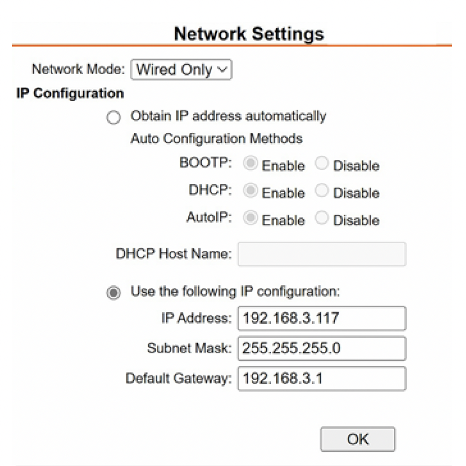
Static IP Configuration
To configure the Static IP settings:
|  |
Modbus/TCP Connection Settings
To configure the channel’s serial settings:
| 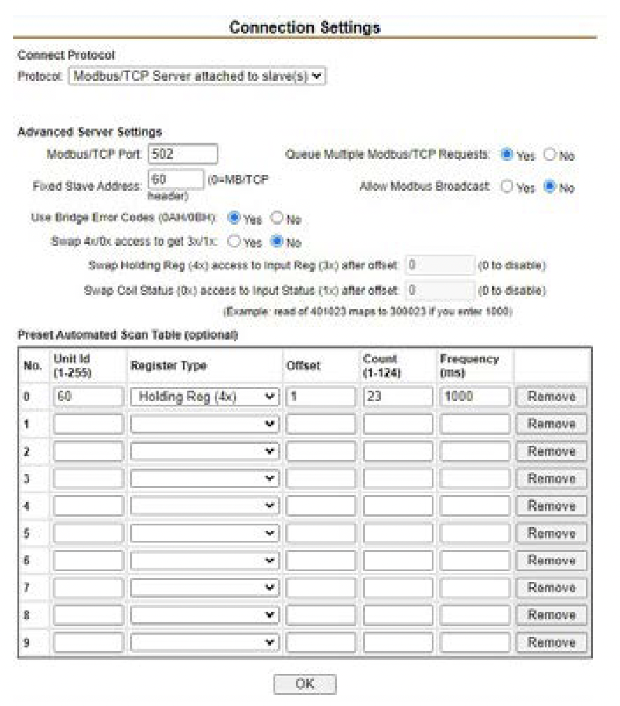 |
| Holding Register | Item | Type | Units | Scale Factor | Contents |
| 0 | Manufacturer | uint16 | N/A | - | "RW" (0 x 5257) |
| 1 | Model | uint16 | N/A | - | "S0" = MK-III, "S1" = AgroMet, "S2" = PVmet |
| 2 | Version | uint16 | N/A | - | 0 x 0170, "01" Map Version, "70" Firmware Version |
| 3 | Air Temperature | int16 | Degrees C | -1 | Measured |
| 4 | Humidity | int16 | % | 1 | Measured |
| 5 | Pressure | int16 | hPa | -1 | Measured |
| 6 | Wind Speed | int16 | m/s | -1 | Measured |
| 7 | Wind Direction | int16 | Degrees | 1 | Measured |
| 8 | Wind Speed 5 Min Avg | int16 | m/s | -1 | Measured |
| 9 | Wind Direction 5 Min Avg | int16 | Degrees | 1 | Measured |
| 10 | Wind Gust (5 Min) | int16 | m/s | -1 | Measured |
| 11 | Wind Gust Direction | int16 | Degrees | 1 | Measured |
| 12 | Rainfall | int16 | Counter | 1 | Measured |
| 13 | Aux Temperature 1 | int16 | Degrees C | -1 | Measured |
| Holding Register | Item | Type | Units | Scale Factor | Contents |
| 14 | Aux Temperature 2 | int16 | Degrees C | -1 | Measured |
| 15 | Soil Moisture 1 | int16 | kPa | 1 | Measured |
| 16 | Soil Moisture 2 | int16 | kPa | 1 | Measured |
| 17 | Soil Moisture 3 | int16 | kPa | 1 | Measured |
| 18 | Solar Irradiance 1 | int16 | W/m2 | 1 | Measured |
| 19 | Solar Irradiance 2 | int16 | W/m2 | 1 | Measured |
| 20 | UV Index | int16 | N/A | 1 | Measured |
| 21 | Leaf Wetness | int16 | % | 1 | Measured |
| 22 | Battery Voltage | int16 | Volts | -2 | Measured |
FCC Compliance Notice
This equipment has been tested and found to comply with the limits for a Class B digital device pursuant to Part 15 of the FCC Rules. These limits are designed to provide reasonable protection against harmful interference in a residential installation. This equipment generates, uses, and can radiate radio frequency energy and, if not installed and used in accordance with the instructions, may cause harmful interference to radio communications. However, there is no guarantee that interference will not occur in a particular installation. If this equipment does cause harmful interference to radio or television reception, which can be determined by turning the equipment off and on, you are encouraged to try to correct the interference by taking one or more of the following measures:
- Reorient or relocate the receiving antenna.
- Increase the separation between the equipment and receiver.
- Connect the equipment into an outlet on a circuit different from that of which the receiver is connected.
- Consult the dealer or an experienced radio/TV technician for help.
This device complies with part 15 of FCC rules. Operation is subject to the following two conditions:
1. This device may not cause harmful interference.
2. This device must accept any interference received, including interference that may cause undesired operation.
Changes or modifications not expressly approved by Hunter Industries could void the user’s authority to operate this device. If necessary, consult a representative of Hunter Industries Inc. or an experienced radio/television technician for additional suggestions.
The following statement is applicable when irrigation controller is used with accessory Wi-Fi device: This equipment complies with FCC radiation exposure limits set forth for an uncontrolled environment. In order to avoid the possibility of exceeding the FCC radio frequency exposure limits, human proximity to the antenna shall not be less than 7.9" (20 cm) during normal operation.
This equipment complies with the IC RSS-102 radiation limits set forth for an uncontrolled environment. This equipment should be installed and operated with a minimum distance of 7.9" (20 cm) from all persons.
Still need help? We're here.
Tell us what you need support with and we'll find the best solution for you.