Residential & Commercial Irrigation
USA
All diagnostic functions are completed via wireless communication between the EZ-DT and EZ-1 decoders. To read decoder information: Manually activate the desired station to energize the two-wire path. ICC2 Manual Operation HCC Manual Operation PC400 …
Support Document
If new firmware versions are released for any of these components, the files will be available on the documents tab on the website (see links below). They can be uploaded to the EZ-DT via a microSD card (32GB or less) located within the battery …
Support Document
The EZ-DT display offers 12 selectable language options. From the HOME Screen, select SETTINGS . Select LANG. Then click then ENTER . Choose a LANGUAGE and click ENTER . The EZ-DT device may be updated after purchase. If a new EZ-DT …
Support Document
Power Input: 4 x AAA batteries Communications: wireless induction, 1" range from EZ-1 decoder to EZ-DT Display: 1.8", full-color, backlit TFT … EZDT - …
Support Document
This guide outlines the application, design, and installation of Hunter’s inline drip products that provide designers, installers, and irrigation managers a new class of irrigation technology. It is written for professionals who have a solid understanding …
Support Document
This chart can help determine the spacing you need for your soil type. SOIL TYPE SAND LOAM CLAY Emitter Distribution - Illustration of how the water is distributed in different soils. Saturation Rate in/hr .75 - 1.25 .25 - .75 .15 - .25 mm/hr 19 - 32 6 …
Support Document
Hunter POINT-SOURCE EMITTERS apply water slowly and directly at the base of the plant to ensure every drop is put to efficient use. They are available in three convenient styles, including self-piercing ¼" barb, 10-32 threaded fitting, and ½" female pipe …
Support Document
Emitter tool for punching a pilot hole, inserting, and removing an emitter. … Emitter tool for punching pilot holes and pellets, inserting and removing an emitter, and cutting tubing. … Pocket Punch … HEMT - Hunter Emitter Multi-Tool … Emitter …
Support Document
Operating Specifications Temperature Pressures Humidity 0 to 140ºF/60ºC up to 200 psi/13.7 bar up to 100% Flow Range Flow-Sync Sensor Diameter Operating Range (Gpm) Minimum* Suggested Maximum** 1" 2 17 1½" 5 35 2" 10 55 3" 28 120 4" 34 195 * Minimum …
Support Document
Wiring the Sensor to the Interface Box The red and black leads from the Flow-Clik sensor are connected to the red and black leads on the Interface Box. A minimum wire size of 18-gauge wire can be used to connect the leads from the sensor to the …
Support Document
Remove the sensor jumper across the two SEN terminals in the controller. Attach the two yellow wires to the 24 VAC terminals. Attach the blue wire to one SEN terminal and the white wire to the other SEN or SEN COM terminal. NOTE: Additional setup steps …
Support Document
The receiver has two LED lights that indicate the state of the system. SENSOR STATUS LED: RED : Sensor is wet (watering disabled) GREEN : Sensor is dry (watering enabled). YELLOW : Sensor is in addressing mode. SENSOR BYPASS LED: RED: Rain sensor is …
Support Document
Tips for Mounting the Sensor -Choose a location such as the side of a building or post. The closer the transmitter is to the receiver, the better the reception. Do not exceed 800' (243 m). -To ensure maximum range in communication, mount the receiver …
Support Document
Manual Test Spindle: Press and hold the manual test spindle to confirm the proper operation of your sensor. Vent Cap and Spindle: Used to adjust reset rate or dry out time for the sensor. Radio Antenna: Transmits a wireless signal to the receiver up to …
Support Document
Flow-Sync is typically installed near the point of connection, in an appropriately-sized FCT Tee. Flow-Sync can connect to the host controller via two direct burial-rated 18 AWG/1 mm wires up to 1000 ft/300 m away from the controller. Flow-Sync can also …
Support Document
Cause Water shut off Controller not configured Faulty Wiring- Use voltmeter to verify red and black wires are connected, and have not been reversed. Damaged sensor- Impeller damage (debris in water) or Flow-Sync electronics damage (lightning) Solution …
Support Document
Quick couplers allow fast access to water while maintaining in-ground durability and vandal resistance. A quick coupler valve is a great tool to use when the rotor does not need to be turned on to irrigate a large area, and it’s only needed for spot …
Support Document
The ICD-HP programmer operates with 4 x AA batteries. The batteries supplied are not rechargeable! … Remove cables and connectors from end of ICD-HP. Pry the yellow flexible yellow boot off the ICD-HP. Turn the ICD-HP over, and remove the 2 screws …
Support Document
The ICD-HP Handheld Programmer is an innovative setup, programming, and diagnostic tool for Hunter ICD and DUAL series decoder products. The ICD-HP may be flash updated to the latest version, with a free download from the product Resources page. Version …
Support Document
If the rain sensor is interrupting irrigation, you can bypass it by using the bypass switch on the front of the controller. Press the Sensor Bypass button to temporarily bypass the sensor status and allow normal controller operation. The Bypass switch …
Support Document
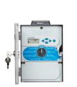
Welcome to the XC Hybrid support section. Find support for the battery powered irrigation controller using the menu. … XC Hybrid Support …
Support Section
The NODE-BT controller offers an easy way to check the battery health of the actual controller without the use of a smartphone. Press the physical BATTERY CHECK BUTTON on NODE-BT controller and the battery indicator LED flashes green or red. 4 green …
Support Document
Calculate the application rate of each similar zone by using the following formula: 231 is going to be the conversion number or constant. The GPH depends on the size of the built-in emitter, Hunter manufactures .4, .6 or .9 GPH (1.35, 2.35, 3.75 l/hr) …
Support Document
Emitter Flow Rate = 1.0 GPH Row Spacing Emitter Spacing 12" 18" 24" 12" 1.6 1.1 0.8 14" 1.4 0.9 0.7 16" 1.2 0.8 0.6 18" 1.1 0.7 0.5 20" 1.0 0.6 0.5 24" 0.8 0.5 0.4 Note: Application rates in inches per hour Emitter Flow Rate = 0.6 GPH Row Spacing …
Support Document